Thursday, 12 June 2014

Week 18 (FYP II): Submission of FYP Report

This the last post of this blog. 

Tomorrow, 13th June 2014, I will submit the following:

  1. The softcopy files related to the GSM Based Speed Monitoring and Detection System to the Supervisor.
  2. The softcopy files related to the GSM Based Speed Monitoring and Detection System to the FYP online website.
  3. A hard cover of the final year project report to the library.
If all goes well, the FYP subject will be completed. 

Nuruddin Ali bin Johari
Student of UNIKL BMI
BET in Mobile Communications.

Sunday, 8 June 2014

Week 15 - Week 17 (FYP II): Final Exam S1'2014

Due to the final exam of s1'2014 semester, I have to halt the final report of the FYP. I will continue writing and finishing the report until the exam has ended.

Sunday, 18 May 2014

Week 14 ( FYP II): Final Year Project Presentation

Objective: To create a poster of the project for the Presentation Day

Analysis/Procedure:

I have finished creating the poster for my project. After the numerous tests made to the prototype are positive and work successfully, together with the poster, I have present to my supervisor to make sure both of them have been satisfied. 


The Presentation Day has been a success. I have presented my project to both of the assigned accessors and they are satisfied with my project. 

Now I have to write the FINAL REPORT for the Final Year Project which I must submit before Friday of week 18.

Sunday, 11 May 2014

Week 12 - Week 13 (FYP II): Prototype Testing

Objective: To integrates all circuits into a prototype.


Analysis/Procedure:


There are four circuits placed in a box. The box is drilled and cut to display the LCD, to mount the push switches and for cables to connect with the power supply source. The box comes with four screws at the bottom to make sure the circuits are secure.


Four circuits inside the box are:

  1. PIC Circuit
  2. 80 KM/H LDR circuit
  3. 110 KM/H LDR circuit
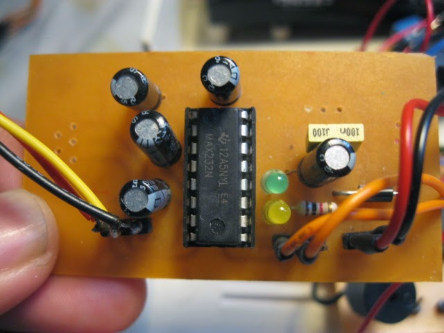
  4. RS232 to TTL circuit


After numerous tests has been done, the objectives of this project has been achieved. The prototype successfully monitors and detects a speed exceeding the limit (as set using SMS). It successfully and effectively transmit and receive the data (alert) via SMS.


The prototype has been implemented using the circuitry knowledge of the author. Lastly, the system has successfully integrates a mechanical device (DC motor of the speedometer) and an electronic device (GSM modem).

Sunday, 27 April 2014

Week 10 - Week 11 (FYP II): RS232 to TTL

Objective: To create a RS232 to TTL converter circuit

Analysis/Procedure:

RS232 is an asynchronous communication protocol that lets you transmit and receive data between DTE (Data terminal Equipment) and DCE (Data Circuit Terminating Equipment) such as modem.  It  is  the  EIA/TIA  (Electronic  Industries  Alliance/  Telecommunications Industry  Association)  that  defines  physical  and  electrical  characteristics  of  the  RS -232 interface.


RS-232 is active low voltage driven interface and operates at between  -12V and +12V for which  signal  is  LOW  or  0  when  voltage  is  higher  than  +3  Volt  and  signal  is  HIGH  or  1 when voltage is lower than -3 Volt. For any voltage falling between +3 Volt and -3 Volts are considered „dead area‟ or indeterminate value. TIA defines the power level for short circuit protection  to  be  100mA,  however  most  RS-232  drivers  will  provide  lower  short  circuit protection. 


Saturday, 12 April 2014

Week 7 - Week 9 (FYP II): The Microcontroller Circuit

Objective: To create a microcontroller circuit.

Analysis/Procedure:

The Peripheral Interface Controller (PIC) is the heart and the brain of this project. The PIC16f877A is a component which easy to install to a circuit board. It can be operational with voltage source from 4.0V to 5.5V. The component is very sensitive towards heat especially when soldering which could lead to component damage. Hence, a PIC housing is used. When soldering the component into a circuit board, the PIC housing must be soldered first since it is able to withstand the heat. Other electronics component needed are;
  1.  Voltage regulator
  2.   22pF capacitor
  3. Crystal (XTAL) oscillator
  4. LED
  5. Male pin 


After the circuit has been completed, the Peripheral Interface Controller (PIC) need to be coded. It takes almost 2 weeks to write the coding since I have a very basic knowledge of programming. After three weeks, the microcontroller circuit is completed. However, the circuit is still need to be tested when integrating with other circuit.
j

Friday, 14 March 2014

Week 5 - Week 6 (FYP II): The LDR Ciruits

Objective: To create a circuit for the light dependent resistor

Analysis/Procedure:

The light dependent resistor (LDR) is used to be the sensor of this project. Initially, the chosen sensor of this project is the proximity sensor. However, after mounting it to the speedometer, it generates an inductive kick back current by the DC motor. 

Inductive kick is very common in motors because of the coils in them. When there is a change in the current of the coils, for example, when the motor being switched off, a high voltage spike will develop. The result makes the proximity when ON and OFF in a wild manner. But in reality, the needle of the speedometer will rotate due to the air pressure from the axel of a vehicle’s tyre rotating. The faster the tyre rotate per revolutions, the faster the needle will rotate (increase of KM/H). Thus, the proximity sensor will work in a speedometer in a real vehicle.

LDR is a passive electronic component, basically a resistor which has a resistance that varies depending of the light intensity. A photoresistor is made of a high resistance semiconductor that absorbs photons and based on the quantity and frequency of the absorbed photons the semiconductor material give bound electrons enough energy to jump into the conduction band. The resulting free electrons conduct electricity resulting in lowering resistance of the photoresistor. The number of electrons is dependent of the photons frequency.


After circuit has complete, the LDR must be mounted to the speedometer display.